- Location:
- Home
- Products
- Carbon fibre components
German process carbon fibre ultra-high speed CFRP rotor sheath
Rotor design for surface-mounted high-speed permanent magnet synchronous motors
Synchronous high-speed permanent magnet motors are characterised by high power density, small
size and high efficiency, and are increasingly used in many applications where high speed is required.
In order to To effectively ensure that the permanent magnets (magnets) of the rotor of high-speed
motors work safely and normally at high speeds, they need to be fixed in a reasonable way. Based on
many years of of practical applications, the use of carbon fibre composite materials, through rational
calculations and process design, is a more ideal solution.
The tensile strength and stiffness of carbon fibre composites is three to five times greater than that of
conventional metallic materials (e.g. steel, aluminium, titanium, etc.); at the same time, carbon fibre
composites are far more elastic in their The allowable strain in the elastic range of carbon fibre
composites is much greater than that of most metallic materials. The following graph compares
the strength performance curves of carbon fibre materials with those of several other materials.

For motor rotors, the magnets (permanent magnets) can be designed to be fixed to the outer surface of the
rotor, usually in one of two ways: either with the common magnets embedded or by attaching the magnets to
the outer surface of the rotor using an adhesive material; however, in either case, there is a high risk of the
magnets being thrown off by the centrifugal force generated by the rotor rotating at high speed. However, in
either case,there is a high risk of the magnets being thrown out by the centrifugal force of the rotor rotating
at high speeds; this therefore limits the motor from achieving the desired high speed. On the other hand, the
Even if the magnets are not completely thrown out of the rotor at high speeds, the very small displacements
caused by the high centrifugal forces may The entire dynamic balance of the rotor can be disrupted, resulting
in significant motor failure or even danger.
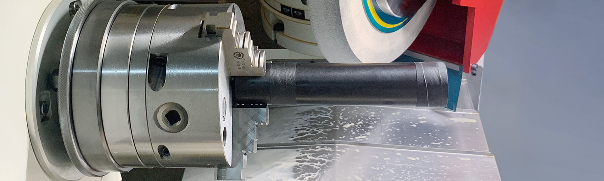
The use of a carbon fibre rotor sleeve solves this problem by wrapping the magnets in a carbon fibre sleeve
and applying a precise preload to the sleeve and magnets. This allows the rotor to operate safely and effectively
at high speeds.

In principle, it is also possible to use metallic materials to wrap the magnets, but due to the properties of the
metallic material itself, when the rotor rotates at high speed to generate a magnetic field, eddy current losses
are generated on the surface of the metallic material and weaken the power of the motor and generate
additional heat, resulting in superimposed losses. Due to the properties of the metal material, eddy current
losses are generated on the surface of the metal material when the rotor rotates at high speeds to generate
a magnetic field, which reduces the power of the motor and generates additional heat, thus increasing the
rotor temperature and causing superimposed losses, or for which a separate cooling system is required.
A separate cooling system is required for cooling. Alternatively, non-magnetic metallic materials can be
used to wrap the magnets, but these materials are more expensive and have no advantage over carbon fibre.
This material has no advantage over carbon fibre.
In addition, for more demanding applications, the carbon fibre material can be laminated in different ways to
achieve the most convenient process, which is not possible with other materials. This is not possible with other
materials.

The following parametric information is required for a carbon fibre rotor design solution.
Rotor construction and the maximum and rated rotor speed
Structural dimensions and density of the magnets
Air gap of the stator and rotor
The temperature at which the motor will operate, etc.
In general, the above parameters will help us to better design the carbon fibre sleeve. The thickness
of the carbon fibre sleeve must match the thickness between the magnet and the coil The air gap
between the magnet and the coil must be matched and the inner diameter of the carbon fibre sleeve
must be smaller than the outer diameter of the magnet in order to create sufficient preload and thus
protect the magnet from being thrown out by centrifugal forces. For special cases where the carbon
fibre sleeve is subjected to greater loads, we have, through many years of experience, added a
protective layer to its surface, with the aim of protecting the overall structure of the carbon fibre The
purpose of this is to protect the overall structure of the carbon fibre sleeve, for example, from damage
caused by knocks during assembly, which may destroy the stress distribution of the entire carbon fibre
sleeve.
We do not recommend that customers rework the carbon fibre sleeves at a later stage as this can lead
to the destruction of the stresses within the carbon fibre composite, which can cause the carbon fibre
to separate and ultimately cause the whole carbon fibre sleeve to be separated. This can lead to the
separation of the carbon fibres and ultimately to the failure of the entire carbon fibre sleeve structure.
We have many years of practical experience in Europe with carbon fibre composites, high speed precision
rotating applications and have supplied high end customers such as manufacturers of high speed motors,
high speed centrifugal molecular We have many years of practical experience in Europe with carbon fibre
composites and high speed precision rotating applications. We hope that our services will add value to your
products. We are always looking forward to it.
